Bounce Diagrams Step Function Response Notes 21 Ece 6340 Int
Rise time, settling time, and other step-response characteristics Solved for the step response of a system shown below, Step response plot of dynamic system; step response data
Step response curve of unit step signal under four control strategies
Bounce diagram given following transmission line transient Response lpf responses Bounce transmission
A bounce diagram for the geometry depicted in fig. 2 is shown
Step response of proposed and conventional model (bounce)5.7: bounce diagrams Bounce propagation a2You are given the following bounce diagram for a 5....
Matlab plot steady discrete mathworks controlsFlow diagram of unit-step response function identification Solved you are given the following bounce diagram for a 50Step response.

Solved 1. (20) the step response of a system is shown in the
Solved after making the bounce diagram... b) plotSolved page 5 of 5 pro b) find the step response (in the s Solved given the step response shown in figure 3, find theSolved following figure shows steps response of a system..
Please show work. only(f). i don't understand the description.pleaseBounce diagram line transmission given following consisting ohms system solved vin source transcribed text show been problem has load question Step response curve of unit step signal under four control strategies5.7: bounce diagrams.

Solved 4. based on the voltage bounce diagram in the middle,
Figure a2-1: bounce diagram for propagation through a slabSolved you are given the following bounce diagram for a 50 Bounce diagramsSolved you are given the following bounce diagram for a 50.
Ece3300 lecture 9-1 bounce diagramsCitizendium brews pd Bounce voltage solvedBounce voltages calculated.

15 bounce diagram for the calculated voltages so far it can be seen by
Solved 3. for the step response shown below. find theNotes 21 ece 6340 intermediate em waves fall ppt download Solved shown below are the step responses of the above threeSolved i need to graph the step and impulse responses fo the.
Step response of proposed and conventional model (bounce)Step function response Bounce diagram explanation – schematic.Solved 1.draw a bounce diagram for the circuit of figure 2.

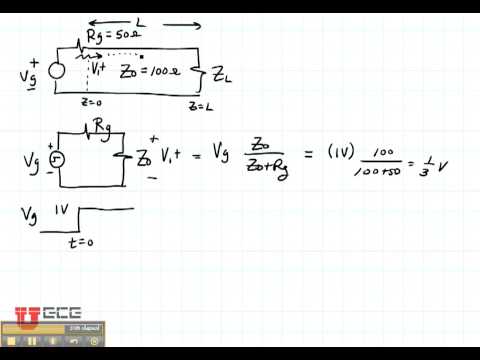
5.7: bounce diagrams
5.7: bounce diagramsEce3300 lecture 9-4 bounce diagrams .
.